

- About
- GreetingHistoryOrganizationApprovalsLocation
- Products
- ProductsGRIP TypeMULTI-FLEX TypeREPAIR CLAMP HINGE TypeREPAIR CLAMP DOUBLE TypeFIRE PROTECTION COVER-GRIP TypeELBOW-REPAIR CLAMP TypeECO-PIPE COUPLINGSLarge Size Custom MadeSHIP PARTS
- Refernces
- Supply PerformanceGlobal PartnersPictures of references
- Tech, Info
- Classification Test RulesLarge-Size Pipe-Coupling Test SceneName of partsStandard of PipeRegistration certificateInstallation
- Contact Us
- Contact UsNewsARCHIVE
-
FIRE PROTECTION COVER-GRIP Type
SINCE 1986 Best Quality Price Satisfaction Timely Delivery YOUNGNAM METAL CO.. LTD.
-
Products
-
FIRE PROTECTION COVER-GRIP Type
-
FIRE PROTECTION COVER-GRIP Type
-
FIRE PROTECTION COVER-GRIP Type
-
FIRE PROTECTION COVER-GRIP Type
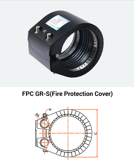
FIRE PROTECTION COVER GRIP PIPE COUPLING
(FPC GR-S)
Fireproof coupling products are designed to minimize human and material damage by preventing secondary accidents due to coupling damage in the event of a fire at the pipe installation site because a fire protection cover is installed on the pipe connection (GR-S) product. , ship cabin, engine, engine room, etc.)
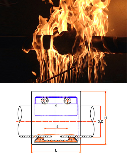
FPC-GR-S
※ You can check by swiping the table left or right (swipe).
| SIZE | O/D (mm) | Range | M | L | ℓ | U | H | W.P | W.T | P (N·m (kgf·cm)) |
|---|---|---|---|---|---|---|---|---|---|---|
| N.D (Inch) | D1 | D2 | Ship | |||||||
| 15A (1/2″) | 21.3 21.7 22.0 | O/D±0.3 | M6 | 57 | 20 | 38 | 40 | 20 | 0.28 | 3~5 (30~50) |
| 20A (3/4″) | 26.9 26.7 27.2 | O/D ±0.5 | M6 | 68 | 20 | 52 | 63 | 20 | 0.32 | 4~6 (40~60) |
| 25A (1″) | 33.4 33.7 34.0 | O/D ±0.6 | M6 | 68 | 20 | 59 | 70 | 20 | 0.35 | 4~6 (40~60) |
| 32A (1-1/4″) | 40.9 42.2 42.4 42.7 | O/D ±0.6 | M8 | 68 | 20 | 68 | 81 | 20 | 0.45 | 10~12 (100~120) |
| 40A (1-1/2″) | 44.5 48.3 48.6 | O/D ±1.0 | M8 | 68 | 22 | 73 | 87 | 20 | 0.5 | 10~12 (100~120) |
| 50A (2″) | 54.0 57.0 60.3 60.5 | O/D ±1.0 | M10 | 94 | 30 | 92 | 109 | 18 | 1.0 | 15~18 (150~180) |
| 65A (2-1/2″) | 66.7 69.0 73.0 76.3 | O/D ±1.0 | M10 | 94 | 30 | 108 | 124 | 18 | 1.2 | 15~18 (150~180) |
| 80A (3″) | 79.8 84.0 88.9 89.1 | O/D ±1.5 | M12 | 122 | 50 | 130 | 144 | 16 | 2.1 | 40~50 (400~500) |
| 90A (3-1/2″) | 98.0 101.6 | O/D ±1.5 | M12 | 122 | 50 | 155 | 171 | 16 | 2.4 | 40~50 (400~500) |
| 100A (4″) | 104.8 106.3 108.0 114.3 | O/D ±1.5 | M12 | 122 | 20 | 155 | 171 | 16 | 2.4 | 40~50 (400~500) |
| 125A (5″) | 129.0 133.0 139.8 141.3 | O/D ±1.5 | M14 | 138 | 55 | 182 | 203 | 12 | 3.8 | 60~80 (600~800) |
| 150A (6″) | 154.0 159.0 165.2 168.3 | O/D ±1.5 | M14 | 138 | 55 | 207 | 229 | 12 | 4.2 | 60~80 (600~800) |
| 200A (8″) | 204.0 216.3 219.1 | O/D ±2.0 | M16 | 176 | 72 | 265 | 297 | 7 | 11.2 | 120~150 (1200~1500) |
| 250A (10″) | 254.0 267.4 273.1 | O/D ±2.0 | M16 | 176 | 65 | 316 | 348 | 7 | 12.9 | 120~150 (1200~1500) |
| 300A (12″) | 304.0 318.5 323.9 325.0 | O/D ±2.0 | M18 | 176 | 65 | 367 | 400 | 5 | 14.9 | 170~190 (1700~1900) |
| 350A (14″) | 355.6 | O/D ±2.0 | M18 | 176 | 65 | 404 | 439 | 5 | 16.1 | 170~190 (1700~1900) |
· N.D : Nominal Diameter (A)
· ℓ : Allowable Shrinkage/Expansion Clearance(m/m)
· D1 : Actual Outer Diameter of Pipe(m/m)
· T : Thickness of the coupling case(m/m)
· D2 : Min./Max. Allowable Limit for Pipe(m/m)
· U : Outer Diameter of Coupling(m/m)
· M : Fastener Bolt Size/Length(m/m)
· W.P : Working Pressure(㎏f·㎠)
· ØA : diameter of lock rod(m/m)
· W/T : Weight Per Unit(㎏)
· L : Coupling Width(m/m)
· W : Gap between pipes when installing
· P : Optimum Locking Torque Value Nm(㎏f·cm)
※ The specifications are subject to change for quality improvement.